Service explanation for JA-82Y 1 Installation in the control panel If you purchased the communicator separately, it should first be installed in the Oasis control panel as follows: The central controller must be completely powerless (disconnect both the battery and the 230V connection)Install the communicator in the central controller and...
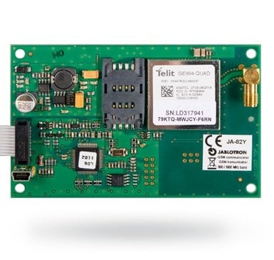
JA-82Y (part 1)
Too much choice? Chat or call us at 085-0160316
There are no products in these categories. Shop on.
Service explanation for JA-82Y
1 Installation in the control panel
If you purchased the communicator separately, it should first be installed in the Oasis control panel as follows:
The central controller must be completely powerless (disconnect both the battery and the 230V connection)
Install the communicator in the central controller and screw it in place and connect the cable to the main board of the central controller.
Place the self-adhesive GSM antenna on the inside of the housing (it can be glued in a suitable place) and connect the antenna to the communicator.
Warning: never switch on the GSM module if the antenna is not connected, this results in serious damage to the GSM module.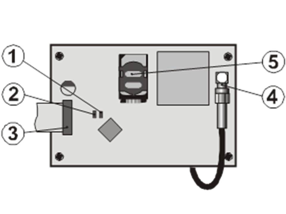
fig. 1 Communicator description:
1.LED signalling connected to a GSM network; 2.LED signalling image transmission; 3. central connection; 4. GSM connection; 5. SIM card
2 First time turning on the communicator
1. If the communicator is installed in the housing and the GSM antenna is fitted then:
2. Load a SIM card. It should be pre-activated (first check that the SIM card works in a mobile phone). If a PIN code has to be entered when the phone is switched on, turn off the PIN function); e.g. Nokia: Menu / Settings / Security settings / PIN code request / Off. The communicator can work with a prepaid card, but for more reliable operation use a subscription.
3. Place the SIM card in the communicator (to open the card holder, slide it slightly upwards)
4. Switch on the control panel (both mains and battery). The communicator's red LED should be on = registering the GSM network; The red LED goes off within a minute = registration successful
5. If the LED starts flashing after a while, switch off the control panel, put the SIM card in a mobile phone and check that the network has sufficient coverage near the control panel and no PIN code is required.
6. Close the switchboard by putting the cover back, the switchboard should be in Service mode - if not, key *0 Service code (Default setting: 8080) with the alarm system switching off.
7. Button 99101 - To set the communicator's text and voice messages to English
8. Key 888 to measure GSM signal strength (a number in the range 1/4 to 4/4 are displayed). It should display at least 2/4 for reliable operation. If the signal is too weak, try moving the PBX or a SIM card from another provider. (It is not recommended to use a high-gain or directional antenna - see Error! Reference source not found. Measure GSM signal strength)
9. If the GSM signal is sufficient, test the operation of the communicator (system operation via a mobile phone, etc), see the instructions below
Warning: If the switchboard is placed near the border with another country where a foreign network can be picked up (e.g. When the signal strength fluctuates), we recommend turning off the roaming setting in the SIM card to avoid high costs. Contact the provider for details.
3 User functions of the communicator
The following text describes all functions of the communicator. The installer could explain these functions to the user if they are applicable in a particular installation.
3.1 Notification of events to the user's phone
The communicator reports events in the OASiS system by sending an SMS and/or calling and sending a voice message. Reporting can be set to up to 8 phone numbers. The most commonly used report variants are preset, but they can be customised.
Notes:
- If used, transmissions to the Alarm Centre have absolute transmission priority
- Calling is usually used to alert the user to a detailed report, sent in an SMS. If SMS messaging is enabled, the communicator first sends all SMS messages before it starts dialing the set numbers.
- Message playback can be terminated by pressing * on the phone. The keypad then switches to keypad and messages are not passed to other numbers.
3.2 Temporarily authorise a telephone keypad as a control panel
It is possible to operate the system remotely by temporarily authorising a telephone keypad as a control panel:
- Dial the SIM card number of the communicator
- After 15 seconds of ringing, the system will respond with a voice menu welcome message and ask for a code.
- Enter an appropriate access code on the device - the master code (1234 by default), a user code or possibly the service code (8080 by default).
As soon as the code is entered, the voice menu will offer basic system functions.
To exit this mode, disconnect. If nothing happens within one minute, the line is automatically disconnected.
The maximum duration of a phone call is 30 minutes.
Notes:
- A landline phone can also be used to remotely control the system in the same way provided it is set to tone dialing (DTMF).
- Do not key in the codes too quickly, each tone takes a time to be sent (depending on the phone and the quality of the connection).
3.3 SMS instructions to control the system remotely
All incoming SMS messages are checked for instructions to the system and are executed immediately. Each SMS instructive must fulfil the following conditions: code_instruction
(valid code space instruction)
Valid code = a valid code of the system (e.g. 8080, 1234)
The factory default instruction texts (editable - see TXT instruction)
| Instructie | Functie | Opmerking |
| SET | Inschakelen | Enabling and disabling the system (in the same way as a control panel) |
| UNSET | Uitschakelen | If the system is already in the desired mode, nothing happens |
| STATUS | Status query | Including GSM signal strength, GPRS connection and ARC communication (shown as MS1, MS2 and MS3) |
| MEMORY | Last event retrieval | This refers to the last 3 events from the system's memory |
| PGX ON | Enable PGX | the PG outputs must be programmed for the |
| PGX OFF | Set PGX off | function: on/off (dmv 237/247) or 2 second switching |
| PGY ON | Set PGY ON | (through 238/248) |
| PGY OFF | Set PGY off | |
| CREDIT | SIM card credit retrieval | Must be initialised before it can be used - see Error! Reference source not found. |
| DINFO | SMS information about the version of the system | SMS on assembly, firmware, and hardware versions, reg. key, remote access, code via OLink |
Tab. 1 SMS commands
For example, when sending : ''code SET" (valid code space SET) the system will switch on (if the system is already on, nothing will change)
Notes:
- Execution of the instruction is confirmed by an SMS reply
- The SMS instruction texts are not case-sensitive and only ASCII characters are allowed
- The SMS instruction texts can contain multiple instructions separated by a comma
- If you send a message and you are not sure whether or not any other text is automatically added (for example, if you are using an SMS internet server) send the instruction in the following way: %code instruction%%
- The valid code can also be entered automatically, see 6.6
3.4 Remote control by unanswered calls
A limited number of instructions can be performed remotely by calling the system from an authorised phone and ending the call before the system picks up the line. In this way, the system can be operated free of charge with a limited number of functions. It is possible to authorise numbers stored in memory M1 to M8 (also used as warning numbers see Error! Reference source not found.
To authorise a phone number place * after the number followed by one digit (1,2,3,8 or 9) - See note in section Error! Reference source not found.
If a call is made by that number, the communicator will generate "* digit" after the first ring. (As if manually keyed in on the control panel). This free control of the system with unanswered calls can include the following functions according to which digit is after the * in the memory:
*1 Enable complete system (= ABC button on control panel)
*2 Enable part A (= A button)*
*3 Enable part A and B or B (= B button)*
*8 PGX on for 2 seconds. (If the PGX is programmed for the pulse function)
*9 PGY on for 2 seconds. (If the PGY is programmed for the pulse function)
Notes:
If the phone rings with caller ID, it cannot be used to terminate the system in this way.
- If the call is terminated before the communicator answers, this function is free.
- A phone that has this free function can also fully operate the system once the communicator has answered and a valid code has been entered (see 3.2). Let the phone ring until the communicator picks up the line.
- If the number programmed for toll-free control does not need to receive system reports, disable reports for this number (see Error! Reference source not found.).
- The *X functions must be enabled in the PBX
- Placing the *X is used when programming a function using a keypad. The OLink software has a special section for this
4 User communicator programming
User settings of the communicator are set by entering sequences from the OASIS system keypad. Selected parameters can also be controlled or set by SMS instructions or via OLink.
System setting is possible only when the control panel is in maintenance mode (if not, key *0 master code - Factory setting 1234). Changes to the values in the communicator are performed by entering programmable sequences (see Tab 7).
Push the # button to exit maintenance mode or to cancel the entry if you enter a wrong code.
If the setting of telephone numbers in maintenance mode is enabled in the control panel settings (sequence 251 of the OASIS control panel), then it is possible to set the following parameters in the communicator's maintenance mode by keying in the sequences listed below starting with 8:
- Set phone numbers M1 to M7
- Assign control codes by texting without entering the code
- Select events to be notified by an SMSmessage and call
- Enable/disable remote access (access or single numbers)
- Measure GSM signal strength
- Limit the number of text messages sent
- Set forwarding of incoming text messages to the first phone number
- Start the GSM dialer
- Record voice messages
- Change the remote access code
4.1 Settings for reporting to phone
The communicator can report system events by SMS and/or calling numbers with a sound signal (often used as a sound signal to start reading an SMS). Reports can be sent to up to 8 numbers.
The most common reports are already set from the factory, you only need to programme the numbers in that place which contains the correct settings. If required, other operations can also be added or deleted. (see 6.4)
Standard settings for numbers M1 to M8
| M | Rapporteert |
| 1 | Alerts and errors via SMS |
| 2 | |
| 3 | Alarm and errors via SMS + calling (if you answer you will hear a siren) |
| 4 | |
| 5 | Alarm via SMS + calling. Switching on and off and errors only via SMS |
| 6 | |
| 7 | Alarm via ringing (if you answer you will hear a siren) |
| 8 | Technical error SMS (e.g. for an installer) |
Tab. 2 Records assigned to telephone number on memory M1 to M8
To programme a telephone number in one of the memory locations M, key in the following sequence when the system is in service mode: 81 M xxx...x*y *0
Where:
M memory location 1 to 8
xxx...x phone number (maximum 20 digits)
*y is a sequence for control via unanswered calls (does not need to be entered)
In a split system, information from all sections (ABC) is reported to the 1st and 8th number of positions, sections AC to numbers 2 to 4 and from sections BC to positions 5 to 7, displayed in OLink software by colour differences.
Notes:
- In a split system, when you change the location of the detector, you adjust the response of the detector. With the enrollment in the mode, you have to react for 1sec and exit it before leaving the service mode. This way the changes are stored in the communicator.
- For automatic time synchronisation via SMS use position 0 in the phone number settings (the position for its own SIM card number). When you change the SIM card this number is automatically erased.
- To delete a number from memory key: 81 M *0
Example 1: key 81 5 777 777 777 *0 save the number 777777777 in memory M5 (alarms are notified by SMS + phone calls with a voice message) Activation/Deactivation is only notified by SMS). Remote access is allowed for this phone number.
Example 2: key 81 1 777 777 777 *8 *0 will store the number 777777777 in memory M1 (alarms are only reported by SMS.) Calling this number will turn on the PgX for 2sec. Remote access is not allowed with this phone number.
Notes:
- Key *9 before the number generates with a "+" for programming an international number
- SMS report consists of: Installation name, operation name, number and name of origin (device or code), date and time. Example: "Report of your Alarm: enabled 47: code Time 01.08. 11:27"
- If other actions or a text should be reported to a specific number, change the setting in the communicator (see 6.7 and tab. 5 the list of events can be reported to your phone and the factory settings)
5 Voice menu for control via a phone
The communicator is equipped with a voice menu for controlling system functions (remote access via a phone must be enabled). The menu has a factory setting and has standard reports in several languages - the desired language can be selected by keying in 991 xx sequence. The voice menu function (fig. 2 Voice menu control ) is as follows:
- After 15 seconds of ringing the communicator will respond with a voice menu welcome message
- After entering a valid code, the voice menu will offer to switch the system on or off. The offer is played once and when you press any key, the current status is reported and the current offer replayed.
- If you press the 9 in the menu, you will hear: "Key simulation" and the phone comes into action as a system keyboard. It stays in this mode and allows you to enter sequences that are confirmed by beeps.
- When you execute and verify the service/maintenance code and if the code is valid, you will hear: "Service mode, keypad simulation". It stays in the mode and you can key in which is confirmed by beeping. If you now key in 892, you will enter the voice message recording menu - see 10 .
- Events that happen remotely are reported once every 5 seconds
6 Installation programming
The easiest way of programming is by means of a PC with the ComLink software or via the Internet at the page: www.gsmlink.cz
Programming is also possible at the control panel:
The control panel must be in service mode , if not key in *0 Service code (default: 8080) while the system is switched off.
Key in the relevant programming sequences - See tab. 7 communicator programming sequences).
To exit service mode press the # key
6.1 Communicator language setting
The language of the texts and voice menu used by the communicator can be set by the instruction: 991 xx
xx is a number of the language - see the following list:
| 01 | EN | Engels | 10 | FI | Finnish |
| 02 | CZ | Tjechisch | 11 | For future use | |
| 03 | SK | Slowaaks | 12 | SV | Zweeds |
| 04 | NL | Nederlands | 13 | FR | Frans |
| 05 | DE | Duits | 14 | HU | Hongaars |
| 06 | PL | Pools | 15 | RU | Russisch |
| 07 | DA | Deens | 16 | TR | Turks |
| 08 | IT | Italiaans | 17 | SP | Spaans |
| 09 | PT | Portugees | 18 | GR | Grieks |
Voorbeeld: Key in 99101 and the language becomes English
Notes:
- Keying in 00 will reset the written and spoken text messages to the factory settings in the currently set language.
- Set the language for editing text in the system (a change of language will change the text to the default setting)
- A change of language in the communicator will automatically change the language in the connected control panels.
- The set language will not be changed if a reset is performed.
Standard setting: 99101 = English
6.2 Measure GSM signal strength
A GSM signal of good quality is required for correct functioning of the communicator. With the series 888, a signal measurement is made of the GSM network. The control panel then shows how strong the GSM signal is with the value ¼ to 4/4 and will repeat every second (beeps at each measurement) In this mode, a suitable location of the control panel (or of the GSM antenna) can be found. Press # to stop the measurements. The signal should indicate at least 2/4. In locations with low signal, we recommend trying another GSM sim card.
Warning: it is not recommended to use a high-gain or directional GSM antenna for better signal. This way, the communicator will only communicate with one GSM base station and the communication will not be stable. Also note that the distance from the antenna to a GSM base station should not exceed 30 Km (even if the signal is strong enough) Time delays in the GSM network can then lead to data transmission errors. (e.g. the timing of the CID protocol)
6.3 Setting telephone numbers and events
The default list of call forwardings and corresponding position in memory M1 to M8 can be changed as follows. (tab. 1)
The complete list of possible forwarding events is shown in the table below.
(Tab. 5 List of events that can be reported to your phone and factory settings.)
It is possible to select whether a forwarding is by SMS only, by call only or and SMS followed by a call Each forwarding has its own default SMS text. These texts can be modified (it can be customised - see 6.8 ).
6.4 SMS report setting
To link operations to reports via SMS key: 82 M uu x
Where:
M phone number on memory location 1 to 8
uu event code 01 to 97 (see tab. 5)
x 0 = no SMS report, 1 = SMS report
Example: If 82 8 03 1 is programmed and a smoke alarm goes off (event 03 in the table), the communicator will send an SMS report to the number in memory location M8.
6.5 Voice message setting
To link actions to reports via voice message key: 83 M uu x
Where:
M phone number on memory location 1 to 8
uu event code 01 to 97 (see tab. 5 )
x 0 = no phone call, 1 = phone call
Example: If 83 1 03 1 is programmed and a smoke alarm goes off (event 03 in the table), the communicator will call the first number stored in memory and keep repeating. Your system will report a fire alarm.
Notes:
- Alarm via call is most commonly used as an audio alert to let the user read the detailed SMS report.
- If used, reporting to an ARC goes for everything if it is active
- To end a playing message press # on the phone's keypad. The keypad then switches to keypad simulation mode and messages are not passed on to other numbers.
6.6 Access code to give command to programmed phone numbers
If you don't want to enter your access code every time you receive an SMS message with an instruction, you can automatically assign an access code in the communicator to a selected phone number. To do this, key: 84 M xxxx
Where:
M phone number on memory location 1 to 8
xxxx Valid code UC / MC / SC
Example: if 83 1 2222 is programmed, the code 2222 is automatically inserted into an SMS message with instructions and sent to the first number stored in memory.
Standard setting: No code
6.7 Remote access for telephone numbers
Remote access is allowed for numbers stored in positions 1 to 8. Programmeersequentie: 85 M x
Waarbij:
M memory location phone numbers 1 to 8
x parameter 1 to allow access - parameter 0 to deny access
Standard setting : remote access allowed for all numbers in position 1 to 8.
6.8 SMS and instruction editing
The communicator contains several pieces of text to generate an SMS report as well as an SMS instruction set. The language of the text can be set - see Error! Reference source not found... These texts cannot be changed on the control panel, but can be changed with the ComLink software, via the Internet (www.gsmlink.cz) or by sending the following SMS instruction: code_TXT_n,text,n,text,......n,text
Where:
code is a valid code (e.g. default codes 8080, 1234)
_ is a space
TXT Instruction to change text
n Text number (0 to 611 see the following table)
, comma (or end)
text The new text (max. 30 characters) which will overwrite the old text. You are not allowed to use a comma or an ending in the new text, a space is allowed.
Notes:
- A single TXT instruction can change multiple texts (limited by the maximum length of a single SMS)
- The communicator is not case-sensitive and it is recommended to use only English ASCII characters. (some networks do not accept non-English characters)
- The communicator creates an SMS with 5 parts: Installation name, operation description, source (code or device) number (01 to 50), source name, time and date.
- The communicator automatically fills spaces, separators and time.
Examples:
If the service code is 8080 then the following instruction: 8080 TXT 20,Remote Peter,21,Remote Karin will be the description (name) of the remotes at addresses 20 and 21. 8080 TXT 605, heating on, 606, heating off changed 2 instructions used to switch the heating using the PGX output (it must then be programmed as on/off.)
6.9 Record voice message
To record a message must be done via the telephone when the system is in service mode. Enter the SIM card number. When the system answers, enter your access code, then key in 9 (keypad simulation) and key in *0 service code or *0 Master code (unless you are in service/maintenance mode) and then sequence 892. The communicator will report that you are in voice message recording mode. You will hear frequent beeps from the receiver; the communicator waits for a key to be pressed:
0 - Repeat all messages
1 - Recording message no. 1 (burglar alarm)
2 - Recording message no. 2 (fire alarm)
3 - Recording message no. 3 (tamper alarm)
4 - Recording message no. 4 (panic alarm)
5 - Recording message no. 5 (fault alarm)
6 - Recording message no. 6 (alarm report) - installation identifier
7 - Recording message no. 7 (any other event)
8 - delete all user recordings = reset to factory-set recordings.
When you key in a 1 to 7, you will hear a beep and you can start speaking. The end of the recording is signalled with a beep and the message is played ags. The communicator then returns to the main menu (regular beeps) and it is possible to record further messages. The length of message No. 6 should not exceed 5 seconds, other messages are 3 seconds long. Press # to stop voice recording and return to service / maintenance mode.
Message No 7 is played at any event you have set for a voice message and which one is not an alarm. The factory-set message is: Another event. That is, it is usually used to inform about the event via SMS. However, it can also be used specifically for a particular event (e.g. a control report of the PG output etc. - it depends on the 83 M uu x settings see Error! Reference source not found.)
Notes:
- Listening to the message can be terminated by pressing the * key.
- To exit the message recording mode, end the call.
- The messages are recorded in a memory that is not erased when the power goes out.
- For events such as switching on/off, the messages "Secure system" , "Not secured system" or "Partially secured" are reported; these messages cannot be changed.
6.10 Set up reporting to a phone
Reports can be set up in the following way:
901 0 All SMS and call reporting disabled
901 1 All SMS and call reporting enabled
901 2 All reporting enabled except for reporting of turning on and off by users 41 to 50 (including codes, cards and remote controls). This allows disabling reporting to recipients of reporting (users, bosses etc).
Standard setting: 9011 All reporting disabled
6.11 Remote access
Remote access with phone on via internet can be turned on or off:
802 0 remote access completely disabled
802 1 remote access from any phone, internet and via Olink
enabled
802 2 remote access from programmed phones, internet and via Olink enabled
Standard setting: Tremote access from any phone, internet and via Olink
6.12 Forwarding incoming SMS messages
This option allows forwarding incoming SMS messages that do not contain valid instructions to the communicator:
801 0 messages are not forwarded, but the communicator stores the last 10 received messages on the SIM card.
801 1 messages are forwarded to the first programmed phone number in memory M1 to M8 (e.g. If only digits are programmed in M5 and M6, then the messages are forwarded to M5). The phone number from which the SMS was received will be displayed at the beginning of the text.
Standard setting: messages are redirected
Note:
- To protect the user from runaway messages (donation SMSes etc.), the redirection is limited to the first 50 SMS messages. The counter can be automatically cleared every midnight, by processing all SMS instructions or by exiting service/maintenance mode.
6.13 Automatic GPRS configuration
When the communicator detects that the SIM card is being changed while it is still powered, the communicator sends an SMS to the YTUN Jablotron server with the network identification. The server then sends back : APN, login, password and its own SIM card phone number.
903 0 automatic configuration disabled
903 1 automatic configuration enabled
Standard setting : automatic configuration enabled
6.14 Confirmation SMS instruction
If the communicator receives a valid SMS instruction, the message sender will be notified whether the instruction has succeeded or not.
904 0 disabled
904 1 enabled
Standard setting: enabled
6.15 Response to incoming calls
The communicator's response to incoming calls can be set as follows:
905 0 the communicator ignores incoming calls
905 1 the communicator will answer after 15 seconds of ringing
Standard setting: answer after 15 seconds of ringing
6.16 Indication for GSM signal failure
This option looks at the connection to the GSM network. If it is enabled then after 15 minutes after GSM network failure an external communication error will be generated.
906 0 disabled
906 1 enabled
Standard setting: disabled
6.17 Time synchronisation via SMS
This setting has the function for synchronising the clock in the exchange. See chapter Error! Reference source not found. for further details.
907 0 sync off
907 1 sync on
Standard setting: on
6.18 Speaker volume
The volume of the connected phone (or intercom) can be set with:
909 x where x is a number from 1 to 9 (max.)
Standard setting: 9 (max.)
6.19 Number called to keep SIM card active
If a prepaid SIM card is used and there is a lack of outgoing calls for a certain time, the SIM card will stop working. This feature provides the following: If no calls have been made after 90 days from the last outgoing call, the communicator will automatically dial the preset number, wait for the call to be answered and hang up after 10 seconds.
910 xx...x *0
Where:
xx...x is the telephone number
Note:
- To delete this number key 910 *0
- It is advisable to call a low-cost service (e.g. weather line etc.) but not toll-free numbers.
Standard setting: Deleted
6.20 Limiting the number of SMS sent
The parameter limits the number of SMS sent to 100 per 24 hours. 50 can be for alarm text messages and 50 can be for other events. This is to avoid receiving a high phone bill.
803 0 limitation disabled
803 1 limitation enabled
Standard setting: enabled
6.21 Automatic credit retrieval from SIM card
The communicator is able to check how much credit is left on the SIM card by requesting it from the network using a recognisable instruction text (by "CREDIT" SMS instruction) or this activity can be requested automatically (with a preset cycle) and if it finds that the remaining credit is lower than the set value, an information SMS is sent. The function is set by sending the following SMS instruction: code_CREDIT_uu..u_xx_yy_zz
Where:
Code Valid main or service code (e.g. 8080 or 1234), the change of parameters is possible with a service code (other codes to request SMS credit "1234 CREDIT")
_ space
uu..u instruction for the GSM network to request credit
xx automatic check periods in days
yyy minimum acceptable credit amount
zz The position in the text where the amount is stated in the received SMS coming from the provider.
Notes:
- If the credit is lower than the set minimum (yyy), text no. 545 will be sent to the phone numbers in memory M1 and M8 to remind the user to top up the credit.
- If only uu..u is entered in the instruction SMS (i.e. no xx, yyy and zz) then the credit will not be checked regularly. The credit is checked immediately and and the uu..u instruction is saved so that in the future the credit can be checked using only the CREDIT instruction.
- If there is more data following the CREDIT, the communicator will remember this and automatically put it in a message when the CREDIT instruction is used again (i.e. the CREDIT instruction must contain at least the uu . u partial on the first transmission) the user then only has to send: code KREDIET
Example: Sending the SMS instruction "code CREDIT" ensures that the balance is checked every 7th day after the SMS is sent and if the balance (starting with the first character in the GSM provider's message) is lower than 50 currency units it will be reported.
Warning: Using a prepaid card in the dialer is risky. Some providers block cards that have enough credit but are not upgraded on time. We therefore recommend always using a SIM card with a subscription!
6.22 Remote programming via SMS instructions
The communicator programs the system remotely by the following SMS instruction: code_PRG_seq_seq, other instruction
Where:
Code valid access or service code (e.g. 8080 or 1234)
_ space
seq programming sequence usually set via the keypad
Notes:
- Only characters that can be typed in on the system keypad (0 to 9, * and #) can be used in the sequences.
- When a valid instruction is received, the communicator will carry out the sequence simulation with keypad entry. A comma in the SMS is considered a pause in the sequence.
- If you want to remotely reprogram the system, it must first be switched off and then put into programming mode.
- The number of sequences in an SMS message is limited by the maximum size of the SMS in the GSM network.
Example: sending SMS 8080_PRG_*08080_201_# will set the output delay to 10 seconds.
6.23 Registration code
You must know the registration code when you first connect via Olink software via the Internet. The code is listed on the label on the communicator panel, but it can also be sent to the mobile phone by SMS. To request a registration code, enter the following: 911 xx...x*0
Where:
xx...x is the number to which the code should be sent.
Note:
- It may take time to receive the code this depends on how busy the GSM network is
- The registration code looks like this: xxxxx-xxxxx-xxxxx-xxxx
6.24 Remote access password
This security key for data communication is a prerequisite for remote access to the system via Olink works. It is set through the following sequence: 894 xxx ...x *0
Where:
xxx ...x is a secure access password that can consist of 1 to 32 digits
Note: If you enter a password, it must be set in the Olink software or by an SMS message. Letters are case sensitive.
Standard setting: 1234ABCD
6.25 Restart GSM communication
After 893 is entered, the communicator disconnects from the GSM network and then re-registers itself. This re-registration does not change all settings in the communicator. It should be used after GSM network errors or data collisions and in some networks it is also required to be used after a blocked SIM card is unblocked by the GSM provider. It is also possible (if the SIM card still has reception) to set the GSM network off by sending the SMS instruction: code GSM
6.26 Dialer reset
With the code 998080 the communicator will return to its factory settings, the default texts will be reset and all reporting turned off.
6.27 Saving the PIN code of the SIM card in the communicator
It is advisable to use a SIM card that does not have a PIN code. If it is not possible to use the card without a PIN, the PIN code can be stored in the communicator with the following sequence (Must be keyed in after the control panel has been activated): 920 PIN*0
Example: if the card's PIN code is 1234 then key in: 9201234*0
Note:
- If the communicator does not register with the GSM network within 1 minute after the PIN code is set (indicated by the flashing red LED), then the PIN code is entered incorrectly or the GSM signal is too weak. In such a case:
- Dial 920*0 in service mode (delete the PIN)
Power down the control panel (230V and battery)
Take the SIM card out of the control panel and put it in a phone. (There should be a connection if the phone is near the control panel).
If you know the correct PIN code and there is sufficient GSM signal put the SIM card back in the communicator. Reconnect the power to the control panel and oer the correct PIN code with the sequence (920 PIN *0) - The communicator then registers with the GSM network. (The red LED remains off within a minute.)
The communicator remembers the PN code and uses it every time the card registers with the GSM network.
If you change the SIM card in the communicator and the old card had a set PIN code, first remove the PIN code with the sequence 920*0 with the control panel in service mode and then change the SIM card.
Warning:The PIN code cannot be changed if the ARC settings are locked.
Standard setting:The PIN code has been deleted
6.28 GPRS log-in parameter
GPRS data communication (Wireless Internet via a GSM network) is used to remotely manage the system via the Internet and for IP reporting to a PAC. To use GPRS data, the SIM card must support it and it must be activated with the provider (contact your provider for details). Then the correct GPRS parameters must be programmed by sending the following SMS to the communicator.
code_GPRS_ x..x_y..y_z..z
Where:
Code is a valid code (e.g. 8080 )
_ space
x..x SIM card APN
y..y username (do not enter if not asked)
z..z password (do not enter if not asked)
Example:
For a T-mobile Czech card: code GPRS internet.t-mobile.cz
Warning:The GPRS parameters cannot be changed if the ARC settings are locked
Standard setting: APN = internet
7 ARC phone numbers
Events can be reported to up to 2 ARCs (which can be independent or ARC2 can work as ARC1's backup). Each ARC can programme its head and backup phone numbers (or IP addresses) with:
Head: 01 p xx....x*0
Backup: 02 p xx....x*0
Where:
p 1=ARC1, 2=ARC2
xxx...x tel. number (max. 20 digits) or the IP address and port - key for example.: 01 2 *8 192 168 001 123 08080 *0
Where:
*8 (auto-converts to #) means an IP address which must have 12 digits and then be followed by the 5 digits of the port number (no separators).
To clear a tel.number / IP address key 01p*0 or 02p*0. If numbers / IP addresses are cleared there will be no reporting to ARC.
Notes:
- the communicator first tries to send data to the main number / address, if this fails the backup tries again to the number / address.
- the ARC address can also be entered as a URL (only via Olink)
Standard setting: all tel. numbers / IP addresses cleared
7.1 Installation (alarm system) ID for ARC use
The installation ID number which each report sends to an ARC can be programmed with: 03 p zz..z*0
Where:
p 1=ARC1, 2=ARC2, 3=IMG
zz..z installation ID number, max. 8 characters (0 to 9 and *1=A to *6=F)
Standard setting: for all ARCs = 0000
Note: If you want to send pictures, key 3 in the p parameter
7.2 Selecting the ARC communication protocol
To select the desired communication protocol key: 04 p x
Where:
p 1 = ARC1, 2 = ARC2
x 0...2 = ARC type
0 = Contact ID, 1 = Jablotron IP, 2 = Jablotron SMS
Notes:
IP CID is the fastest of all the above protocols and it allows very frequent checking of communication with the ARC (e.g. Every 5 minutes)
The Contact ID protocol can be used with ARCs connected by landline (if they support Contact ID)
If the ARC does not support SMS CID or IP CID, please contact your local distributor for details and how to upgrade the ARC.
Standard setting: ARC1 - Jablotron IP, ARC2 - Jablotron SMS
7.3 Selection of events reported to the ARC
From this sequence you can select which events should be reported to the ARC: 05 p uu xWhere:
p 1 = ARC1, 2 = ARC2
uu Event code 00 to 97
x 0 = no report, 1 = report
The report to the ARC consists of:
- Premises number, event code, section, source number.
- Section: 01 is set for all reports
- Partitioning system for switching on and off: 02 = A, 03 = B
- No partitioning system: 01=ABC, 02 = A, 03 = AB
Notes:
- Events to the ARC are reported at section identification
7.4 Check ARC communication - perodic or fixed
This sequence is used to determine whether periodic transmission takes place at a given time according to 07 p hhmm, or periodically according to 07 p hhmm settings. 06 p x
When:
p 1=ARC1, 2=ARC2
x 0= with a period according to 07 p hhmm
1= at the set time and according to 07 p hhmm
Standard setting: With a period after the previous report
7.5 ARC communication control period
This sequence programmes how often the communicator's contral is performed: 07 p hhmm
Where:
p 1 = ARC1, 2 = ARC2
hh hours
mm minutes
Notes:
- Monitoring reports are not sent in service mode.
- Jablotron IP protocol allows a very frequent checking of ARC communication (even every 5 minutes in practice).
- When 00:00 is set, the communication check is not performed.
Standard setting: 23:59 (hour:minutes)
7.6 Enable ARC reporting (ARC2 backup ARC1)
This setting allows to set the reporting to ARC1 or ARC2 and whether ARC2 is a backup to ARC1: 08 p x
Where:
p 1=ARC1, 2=ARC2
x 0=off, 1=on, 2= ARC2 is a backup for ARC1
(2 can only be entered at ARC2)
Notes: If ARC is a backup to ARC1, data will only go to ARC2 if forwarding to ARC1 has failed. ARC2 will also receive an additional report "Communication error to ARC1" in addition to the reports already available to send.
Standard setting: both ARCs = off
7.7 Store reports sent to ARCs in memory
This option activates that each successful report sent to any ARC is stored in internal memory:
001 0 disabled
001 1 enabled
Note: It is advisable to disable this option. This saves a lot of space in the central controller's internal memory. However ARC communication errors can then be stored because then it can be assumed that each notification was sent successfully. If it is not successfully sent within 110 seconds of the attempt it will be reported and stored in memory.
Standaard instelling: uitgeschakeld
7.8 Indication of an ARC communication error
Turns on the indication and reporting of a communication error of an unsuccessful notification within 110 seconds of starting to send to an ARC:
002 0 communication errors not indicated
002 1 communication errors indicated
Notes:
- The communicator continues the attempt to deliver the notification to the ARC even after a communication error has been displayed. (If the data is delivered then the communication error indication stops)
- For communication control the maximum delivery time (confirmation from the ARC) is 300 minutes. For any other notification, the notification must be acknowledged by the ARC within 110 seconds after the notification starts (if not, a communication error is generated)
Standard setting: communication errors not indexed
7.9 URL / IP address for data transmission
The communicator supports transmission of special data (e.g. visual information from the JA-84P) from the system from a set IP address, which can be set by keying in: 013 xx..x*0
Where:
xxx...x is the IP address and port - item format
Example:
013 *8 192 168 021 123 07070 *0
Where:
*8 (auto-converts to #) means an IP address which must have 12 digits and must be followed by the 5 digits of the port number (no separators).
To clear the IP key 013*0.
Notes:
- If there are no devices that support this function, do not set an IP address.
- The address can also be entered in the URL format via OLink, the control panel only knows numbers.
Standard setting: URL - lib1.jablotron.cz:7070
7.10 Locking the ARC settings
All settings that affect forwarding to an ARC can be locked with a digital code: 091 xx..x*0
Where:
xx...x is your code (4 to 8 digits)
Notes:
- when exiting service mode after entering a code, all settings related to ARC communication will be locked (see the list in section 13).
- If ARC programming is locked, it can be temporarily unlocked by entering code 092 xx..x *0 where xx..x is the lock code. After exiting service mode, the settings are locked again.
- The ARC settings can be permanently unlocked by entering the sequence 091*0 (the code can only be cleared when the ARC setting is unlocked).
Standard setting: ARC settings unlocked
7.11 Repeated ARC communication
The communicator tries to send the report to the general telephone number. If this fails, it tries the backup number and in case of failure, the communicator will repeat the attempt with a delay set by the next sequence: 0001 p mmss
With:
p 1=ARC1, 2=ARC2
mmss time in minutes, seconds
Standard setting: 15 seconds
7.12 Number of repeated attempts
Determines how many times in a row the communicator will try to send information to the ARC after an unsuccessful attempt. It is possible to perform up to 9 repeated attempts. This can be set by the following sequence: 0002 p n
Where:
p 1=ARC1, 2=ARC2
n 1 to 9 attempts
Standard setting: 2 attempts
7.13 Integrated image transmitter module
The communicator contains a built-in module for receiving images coming from the JA-84P. The device must be set up properly for successful transmission of images to the server (see 7.10 ) The Jablotron image display server can be found at http://img.jablotron.com.
IP address for image transmission:
URL: lib1.jablotron.cz:7070 IP: 77.104.220.129:7070
Warning: The setting of the changed parameters will only take effect after you leave service mode.
Signalling image transmission on the module:
- When images are taken by a JA-84P, they are immediately sent to the GSM communicator and then to a secure server (if set up).
- Transmission from a PIR to the communicator is indicated by the green LED 1 remaining permanently lit (on the left side under the SIM card holder) see fig. 1 Communicator description: .
- Transmission to the server is indicated by a flashing green LED.
- Successful transmission is confirmed by a long green-LED flash and unsuccessful transmission is confirmed by rapid flashes of the green LED. Successful transfer from the GSM communicator to the server is confirmed by a long flash of the red LED, failed transfer is confirmed by flashing of the red LED.
Notes:
- The total time of transmission to the server is about 20 seconds.
- If the signal is weak, the transmission may take longer (the lost data is sent repeatedly). Each image contains the date of processing and the time when it is taken by the central controller's internal clock.
- The synchronisation of time from the time the batteries are inserted in a JA-84P takes 60 minutes.
7.14 Updating the communicator
The communicator can be updated by an authorised person. (e.g. firmware, language and voice settings). The current firmware can be accessed at www.jablotron.com. Before updating, save the communicator settings in the Olink database. For updating, it is necessary to use one of these interface cables: JA-80T, JA-80BT or JA-82T and the programme Olink (v.2.0 or higher). Updating with a JA-82T is faster. Be careful not to do anything while updating (do not disconnect or do anything on the PC) and wait until the end.
Restart the communicator after updating via the 893 sequence, or turn off the main switch and battery and turn them back on after a few seconds. Then wait for 1 minute. During this procedure please do nothing with the system until the red LED stops shining.
Updating can change the system's registration key which you need for remote access via the internet.
Click here for part 2